Scanning Electron Microscope
Standard Operating Procedure: SEM
Section 1 – Process or Experiment Description
This Standard Operating Procedure (SOP) outlines the proper use of the Nova Scanning Electron Microscope (Nova NanoSEM 450). The Nova Scanning Electron Microscope (SEM) is a high resolution scanning electron microscope intended for sample characterization. In addition to the powerful combination of advanced optics (including a two-mode final lens), SE/BSE (Secondary Electrons/Backscattered Electrons) in-lens detection and beam deceleration, the Nova NanoSEM 450 series introduces a new suite of latest generation, high sensitivity, retractable SE/BSE and STEM detectors, as well as versatile SE/BSE filtering capabilities, to best optimize the information of interest. Intelligent scanning modes are available to minimize imaging artifacts.
All standard laboratory safety protocols must be followed throughout this procedure. While not all safety rules are explicitly stated within this SOP, they are covered in the required safety training sessions that must be completed prior to beginning any lab work. For instance, all personnel must wear appropriate lab attire, including an approved lab coat, safety goggles, closed-toe shoes, and clothing that covers all exposed skin, including the legs. A copy of the laboratory’s minimum safety requirements can be found in the SOP binder for reference.
Section 2 – Hazards General
N/A
Section 3 – Routes of Exposure
N/A
Section 4 – Process Steps
4.1. Working instructions
4.1.1. System Startup
After logging in the Badger, the SEM computer will be ON.
4.1.2. Sample Preparation
- If the sample is nonconductive (plastic, fiber, polymer or other substance with an electrical resistance greater than 1010 ohms) the specimen can be coated with a thin layer (\~10-15 nm) of gold using the Cressington sputter coater. This conductive layer will help to reduce sample charging and improve image quality. If no coating is desired as it might alter the specimen, “Low Vacuum” mode can be used to stabilize the specimen for observation.
- Mount the sample on a sample holder using carbon/Cu tape, or if the holder has clips, tighten the clip with a screwdriver to secure the sample. Be sure the clip holds the sample securely and that the clip is not obscuring any area that you intend to image. The specimen must be electrically grounded to the sample holder to minimize specimen charging.
- Insert the stub of the sample holder into the specimen holder and secure the stub with a hex-wrench.
- Check whether the sample will fit through the load lock door using the
load lock door emulator. If the sample is small enough to fit through the load lock door, then you can use the load lock procedure to load the sample. If the sample is too big, then you will have to vent the main chamber door.
4.1.3. Loading your sample
You can load your sample through the load lock or the main chamber.
4.1.3.1 Loading Sample through Load Lock
- Vent the load lock by pressing the button labelled V (vent) and then lift and swing open the load lock lid.
- Place the sample on the carrier in the load lock and then insert the rod into the sample carrier compressing the spring on the rod. While holding it in place, turn the manipulator to lock the carrier in place and then place the rod into the parking position to prevent the rod from slowly creeping forward.
- Close the load lock lid and press the button labelled P (pump), which will pump the load lock and move the stage into the loading position. Once the load lock is pumped and the stage is in place, the OK button will light up and the gate valve interlock will release, allowing the door to the main chamber to be opened.
- Turn the gate valve knob from LOCK to UNLOCK and then carefully pull the knob bar fully out from the first mark to the second mark. Turn the gate valve knob from UNLOCK to LOCK.
- Move the loading rod from the parking position and into the chamber until the sample carrier engages with the stage at the end of travel. Turn the rod counterclockwise to the base of the slot, pull the rod to the back of the slot, turn it clockwise out of the slot and then withdraw it back to the parking slot.
- Close the gate valve by turning the knob bar to the UNLOCK position, pressing the knob in to engage the valve over the opening and then turn the knob to the LOCK position to secure it. Leave the load lock under vacuum.

4.1.3.2. Loading Sample through Main Chamber
- Click the Vent button and then click Yes when the confirmation box appears. This will begin venting the chamber and move the stage into position. Venting will take around 5 minutes to complete. There is no pressure gauge that will read when the chamber is at atmospheric so you will simply have to wait and then try opening it.
- Once the chamber has finished venting, open the specimen chamber and insert the specimen holder with the sample into the slot on the stage.
- Close the specimen chamber. Check to see that the proper vacuum mode is selected and click the Pump button.
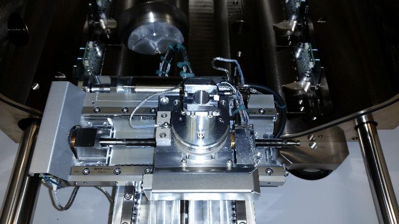
4.1.4. Stage Movement – Navigation
- Before you do any navigation, select the Stage menu and check that Touch Alarm Enabled and External Current Measurement are both checked. These need to be active in case you drive the sample into the detector. With these enabled, the stage will stop as soon as it touches the detector, preventing significant damage. Nonetheless, be careful not to crash your sample into the detector.
- Move the stage up to the 5mm working distance line. This process should be done carefully since the SEM software does not know the relative stage-to-column distance until you link Z to the working distance later. Make sure the camera (4th quadrant) is working.
- To move the stage, open the Navigation page and select the Coordinates tab. In this tab, you can control the x, y, z, tilt, and rotation of the sample stage.
- There are three modes for changing the position: actual, target, and relative.
- Actual mode displays the actual position coordinates in the edit box.
- Target mode activates when clicking a stored position or when editing a coordinate value.
- Relative mode is used to move a stage by a given value and to repeat it several times if needed.
- In order to move a stage, select the Actual mode and enter a value into the edit box and click the Go To button. If you wish to stop the stage while it is in motion, click the Stop button (the Go To button becomes the Stop button when the stage is in motion) or press the Esc key. Start by moving up 5-10mm at a time while keeping the mouse over the stop button in case the stage goes above the 5mm working distance line. The safest way to move the z-stage in order to avoid crashing into the detector is in the live camera quad (Quad 4), hold down the scroll wheel and drag the mouse up or down to move the stage in that direction.
- Adjust so that the top of your sample is roughly aligned with the 5mm line.
4.1.5. Stage Movement – Take Nav-Cam Photo
- Select the Stage menu, select Take Nav-Cam Photo. If the function does not work, try clicking on the Nav-Cam quad (Quad 3) and then try again. Or instead of selecting Take Nav-Cam Photo, select Move Stage to Nav-Cam and once the stage has moved into position select Take Nav-Cam Photo.
- Once the Nav-Cam photo is acquired, it can be used for navigating in the x- and y-plane. Either drag the cross over a desired feature in the image of the sample, or double click on a feature and the stage will move to center that position under the detector.
4.1.6. Imaging
- Wait for the chamber pressure to reach 4e-5 Torr.
- Set the voltage (High Voltage) and current (Spot) to your preferred settings.
- Turn on the beam by clicking the Beam On button.
- Select Quad 1, which should be set to the Everhart Thornley Detector (ETD), and click the pause icon to begin imaging.
- Adjust the contrast and brightness using the control knobs behind the keyboard or by selecting Auto Contrast Brightness (tool bar icon or press F9).
- Set the dwell time and resolution for imaging by making adjustments in the tool bar or by selecting one of the presets.
- Find a feature that you can use for focusing and then use the control knobs behind the keyboard to adjust the magnification, focus and stigmator to optimize your image.
- If you want to use the Through Lens Detector (TLD), select Quad 2, which should be set to the TLD, and click the pause icon to begin imaging (doing so will automatically pause Quad 1 as the SEM switches the detector. When using the TLD you have the option of changing the lens mode between Field-Free (the default mode for ETD) or Immersion (used for ultra-high resolution imaging).
- To capture an image, click on the Photo button or press F2.
- When prompted to save your image, save to your folder in the User SEM Images folder on the Litho-PC. When you are finished imaging switch to the Raith computer and copy your files from User SEM Images to your folder in the NanoFab01 shared drive. DO NOT use a flash drive on either computer and DO NOT try to access the internet. You can retrieve your files from the NanoFab01 folder on any of the computers in the wipe down room.
4.1.7. Unloading your sample
4.1.7.1 Unloading Sample through Load Lock
- Turn off the beam by clicking the Beam On button.
- Check that the load lock is properly closed and press the P button, which will pump the load lock if it is not already at vacuum and move the stage into the loading position. Once the load lock is pumped and the stage is in place, the OK button will light up and the gate valve interlock will release, allowing the door to the main chamber to be opened.
- Turn the gate valve knob from LOCK to UNLOCK and then carefully pull the knob bar fully out from the first mark to the second mark. Turn the gate valve knob from UNLOCK to LOCK.
- Move the unloading rod from the parking position and into the chamber until it meets resistance at the start of the slot. Turn the rod counterclockwise to the base of the slot and push the rod forward to the front of the slot, inserting it into the sample carrier. Turn the rod clockwise to lock the sample carrier onto the rod and then withdraw it back to the parking slot bringing the sample out of the main chamber. Warning: Be sure to put the rod into the parking position at the end; turning it the other way disengages it from the rod and the spring will fling the sample carrier into the gate valve.
- Close the gate valve by turning the knob bar to the UNLOCK position, pressing the knob in to engage the valve over the opening and then turn the knob to the LOCK position to secure it.
- Press the V button to vent the load lock. Once vented the lid can be opened and the sample carrier can be released by turning the rod bar to the far left.
- Remove your sample from the load lock.
- Close the load lock lid and press the P button to evacuate the loader chamber.
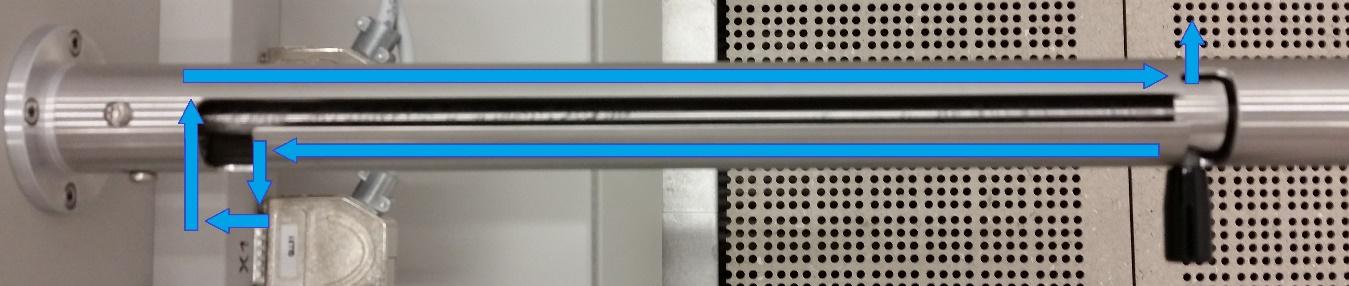
4.1.7.2. Unloading Sample through the Main Chamber
- Turn off the beam by clicking the Beam On button.
- Vent the chamber
- Remove your sample from the chuck.
- Close the chamber door and pump down. Wait for the chamber to fully pump down (check the green status).
4.1.8. Cleanup and Waste Disposal
- Tidy up the area.
- Throw away the used tape into the trash can.
Section 5-Allowed Activities
- Users may open the chamber and insert the low vacuum detector, but only if they have been trained on how to do so.
- Users may open the chamber and change the sample holder setup on the stage, but only if they have been trained on how to do so.
Section 6-Disallowed Activities
-
Users should never disable the touch alarm or the external current measurement.
-
No Magnetic materials are allowed when using the immersion mode.
Section 7- What to watch out for during operation
- Users should be sure that the chamber pressure is less than the 4e-5 range before turning on the beam.
- Users should not adjust the settings for the source tilt and alignment.
Section 8- Common Troubleshooting Tips
- If the image shifts whenever the focus is adjusted, try adjusting the lens alignment, though only if you’ve been shown how to do so.
- If a user is seeing a lot of charging, they could try switching to another detector, or changing the detector setting to backscatter electrons or custom mode.
- If a user is seeing a significant amount of image drift, they should try pausing everything and waiting about 10 minutes before trying to image again.
- If controls are not working properly, try closing and then restarting the software. Log in to the software as “user” with password “Hilda001”.
Section 9 - When to call staff?
- If the cooling water is not flowing.
- If your sample gets stuck in the load lock door.
- If the stage position for loading from the load lock is not correct.
- If none of the common troubleshooting tips can fix a problem.
Section 10-Badger Criteria
Report Problem:
- If none of the common troubleshooting tips can fix a problem.
Shutdown:
- If the cooling water is not flowing.
- If your sample gets stuck in the load lock door.