Bruker Optical Profilometer
Standard Operating Procedure: Optical Profiler
Section 1 – Process or Experiment Description
This Standard Operating Procedure (SOP) outlines the proper use of Bruker ContourGT-I 3D Optical Profiler. The Bruker Optical Profiler is a fully automated and programmable optical interferometric microscope that can be used to measure and map surface features in 3D. The system features an automated tip/tilt optical head, to enable measurements over a range of angles while minimizing tracking errors.
All standard laboratory safety protocols must be followed throughout this procedure. While not all safety rules are explicitly stated within this SOP, they are covered in the required safety training sessions that must be completed prior to beginning any lab work. For instance, all personnel must wear appropriate lab attire, including an approved lab coat, safety goggles, closed-toe shoes, and clothing that covers all exposed skin, including the legs. A copy of the laboratory’s minimum safety requirements can be found in the SOP binder for reference.
Section 2 – Hazards General
| Hazard | Hazard Sign | Hazard Description |
|---|---|---|
| Mechanical Hazard Pinch Point | 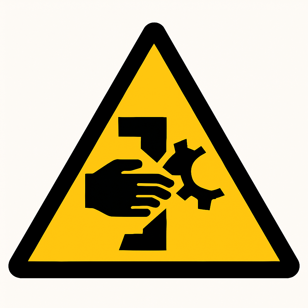 |
The optical profiler is equipped with a motorized stage that can create pinch points – areas where a person’s fingers can get caught or crushed. Do not move the stage with your hands near it. |
Section 3 – Routes of Exposure
N/A
Section 4 – Process Steps
4.1. Working instructions
4.1.1. System Start up
- Turn on the power to the system from the controller. The green ON button will be illuminated.
- Open the Vision64 software.
- Make sure there is enough space between the objective and the sample so that a crash will not occur. Select Continue.
- Make sure the turret is clear of the stage and all samples. Select Continue.
- If necessary, select Initialize XY in the settings for the XY stage to initialize the XY stage and select Initialize Z in the settings for the Z stage to initialize the Z stage.
4.1.2. Loading your sample and alignment
- Place the sample to be measured on the stage directly under the objective. Be sure it is oriented in a way you want it measured as the stage does not rotate.
- In the XY control panel under Instrument Control, select the speed at which you want to move the sample stage and drag the red circle in XY control from the center of the cross-hair to move the stage to position your sample under the objective.
- In the Z control panel under Instrument Control, select the speed at which you want to move the objective lens. Drag the red mark in Z control up or down to adjust the height of the objective in order to bring the sample features into focus. WARNING: Constantly monitor the gap between the objective lens and sample while adjusting the Z position. Crashing the objective lens into the sample will seriously damage the objective.
- The sample is in focus when you observe regularly spaced black and white fringes on the screen.
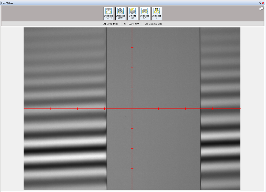
- Portions of the image will appear red when the detector is saturated. You can manually adjust the intensity under Instrument Control or select Auto for an automatic adjustment. Unselect Auto after each auto intensity adjustment.
- In the Tip Tilt control panel under Instrument Control, select the speed at which you want to move the objective. Drag the red circle in Tip Tilt control from the center of the cross-hair to adjust the objective. You need to adjust the tip and tilt such that the fringes are oriented perpendicular to any step features and expanded until there are around 5 fringes on the screen.
- Adjust the Z-position to refocus such that the brightest fringe is in the middle of the screen.
- Adjust the light intensity when necessary.
4.1.3. Collect Measurement Data
- In Measurement Setup, select the measurement mode. VSI/VXI (vertical scanning interferometry) is used to measure a range of surfaces while PSI (phase shifting interferometry) is used to measure smooth, continuous surfaces. There are also options for intensity and thick-film measurements.
- Select the objective (5x or 20x) and magnification (0.55x, 1x, or 2x) you intend to use for measurements. This will determine the measurement area and the resolution of features you are able to measure. Do not attempt to move the objectives by hand.
-
In Measurement Settings, set the backscan (distance the z-stage will move up before measuring) and the length (distance the z-stage will move down before when measuring). The total range of the measurement will be the backscan and length together. If you are measuring in PSI mode, you will not set the range of the measurement.
-
You may also set the profilometer to take multiple measurements and average them. If you wish to measure a larger area, you may select Stitch and set the parameters for stitching.
- Once your measurement parameters are entered, click Single Acquisition to make the measurement. Do not touch or bump the table holding the ContourGT while it is making a measurement as any wobbling could ruin the measurement.
4.1.4. Data Analysis
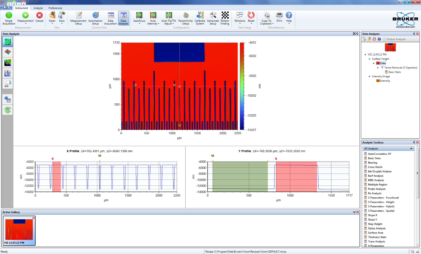
- After the system has made a measurement, the software will switch to the Data Analysis window. Note: There are many options for filtering and analyzing data available in Data Analyzer. For information on the different options consult a Bruker manual.
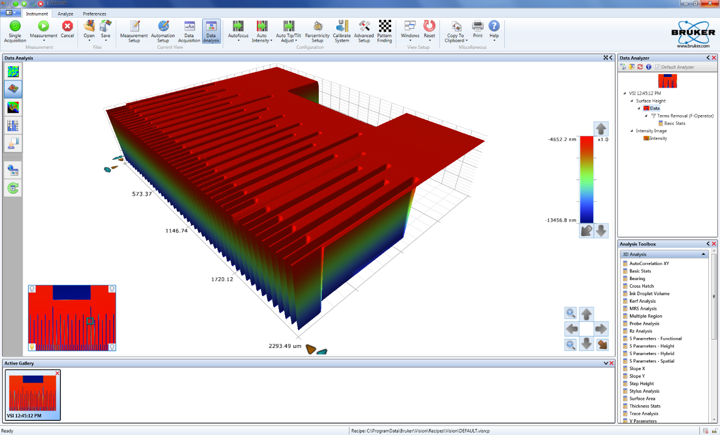
- There are multiple views one can use to perform measurements, such as 2D or 3D. Change the view using the tab on the left.
- In the 2D view measurements can be made along cross-sections on the X and Y-axes. These can be moved around the 2D field. Make measurements by moving the R and M cursors to positions you wish to compare.
- In the 3D view measurements can be made between points set by right-clicking on the 3D field.
4.1.5. Save Data
Save the data set using the file operation functions. Save → Dataset. You should save your data to your own folder in the NanoFab01 network drive either in the XML or Bit map format.
4.1.6. Unloading sample and Shutdown Tool
- Remove your sample. Move the objective up first if it is too close to the sample.
- Close the Vision64 software.
- Turn off the power to the system from the controller.
- Clean up the work area.
Section 5- Allowed Activities
Users should only attempt to make measurements with the tool configured as it is. Anything that requires a different configuration should not be attempted without first consulting cleanroom staff.
Emergency stops should not be necessary for this tool, but if circumstances ever arise where it is necessary to perform an emergency stop, do so by pressing the red EMO button on the tool’s controller.
Section 6-Disallowed Activities
Never try to move the Objectives with hand. Doing so will damage the Objectives.
Users should not attempt to calibrate the tool. If they do not believe the tool is properly calibrated they should inform the cleanroom staff.
Section 7- What to watch out for during operation
Ensure that the objectives are raised high enough to easily clear your sample. Always ensure that objectives will not strike your sample. Doing so can result in damage to the objectives and it costs close to $10,000.
Be mindful of the limits your sample might impose on measurements. Rough surfaces, non-reflective surfaces and multiple materials with different reflectivity can affect or hinder measurements.
Section 8 - Common Troubleshooting Tips
If something is not responding, attempt to close and restart the software. Also, reinitialize the stages.
Section 9- When to call staff?
If the stages stop working, or the light is no longer working.
Section 10- Badger Criteria
Report Problem:Shutdown:
If the stage is not working. Report this in Badger and send a message to staff.