Oxford 80 RIE
Section 1: Hardware Description and Principle of Operation
The Reactive Ion Etcher (RIE) uses a radio-frequency-powered electromagnetic field to generate a plasma in a vacuum chamber. Gasses pumped in while the RF power is active are ionized and bombard the sample- removing material through both chemical and physical mechanisms.
Section 2: General Hazards
| Pictogram | Description |
|---|---|
 |
Radio-frequency Energy/ Radiation |
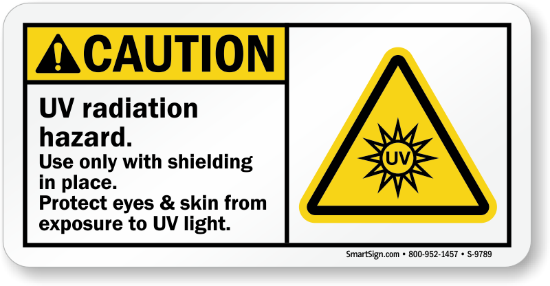 |
Ultraviolet Radiation |
 |
Mechanical Pinch-Point |
Note- If you are sensitive to magnetic fields (eg- use a Pacemaker) please consult with tool manager. (There are magnets in the turbo pump at the tool rear)
Note On Hazardous Gasses:
Be aware that hazardous flammable and oxidizing gasses are used in the RIE tool. The gasses are safely contained, and the lab is equipped with a Toxic Gas Monitoring System (TGMS)- but always be alert and aware of any unusual tool behavior. Contact staff immediately with concerns. Evacuate the building immediately if the TGMS Blue Light Alarm sounds and encourage others to do so too. If the TGMS Yellow Light Alarm sounds, evacuate the cleanroom. If you ever smell anything unusual during venting, immediately close the tool and contact staff.
Any process recipe using a double-valve interlocked Hazardous Gas needs to incorporate a sufficient inert purge step afterwards (5 minutes, 100 SCCM Argon). The double-valve interlocked hazardous gas on the RIE is Methane (CH4).
Oxygen (O2) and flammable gasses must never mix in the chamber. On this tool, the flammable gas is Methane (CH4).
| Gas | GHS Labels | Hazards |
|---|---|---|
| Oxygen (O2) |   |
-Gasses Under Pressure -Danger -Oxidizing! |
| Argon (Ar) | |
-Gasses Under Pressure (may displace oxygen) -Warning -Simple Asphyxiant |
| Methane (CH4) |  |
-Gasses Under Pressure (may displace oxygen) -Danger -Flammable! |
| Trifluoromethane (CHF3) |  |
-Gasses Under Pressure (may displace oxygen) -Warning -Specific Target Organ Toxicity - Single Exposure |
| Sulfur Hexafluoride (SF6) | |
-Gasses Under Pressure (may displace oxygen) -Warning |
| Tetrafluoromethane (CF4) | |
-Gasses Under Pressure (may displace oxygen) -Warning |
For Full MSDS Information, Visit:
O2: https://www.airgas.com/msds/001043.pdf
Ar: https://www.airgas.com/msds/001004.pdf
CH4: https://www.airgas.com/msds/001033.pdf
CHF3: https://www.efcgases.com/wp-content/uploads/2024/09/EFC-Trifluoromethane-SDS-EF-004.pdf?x83664
SF6: https://www.airgas.com/msds/001048.pdf
CF4: https://www.airgas.com/msds/001051.pdf
Section 3: Routes of Exposure
Inhalation (always make sure tool has successfully completed automatic venting cycle)
Eye exposure (mitigated by filter, do not tamper with viewport or stare into plasma for lengthy periods)
Section 4: Approval and Training
Before using the tool, all users must have already been approved to access the cleanroom facility. While using the tool, users must adhere to all rules outlined during cleanroom orientation and in the facility manuals. Only users that have been qualified may use the tool.
In order to become qualified to use this tool, a user must:
- Submit the formstack request(s) for their etch process(es) and receive written approval
- Attend an in-person training session
- Read this SOP and sign the “Signature” page
- Demonstrate competence during an individual qualification session.
- Join the #icp_rie Slack channel
- Submit MSDS sheets for all materials to the tool manager and receive written approval
Only the tool manager may train and approve new users. Any new materials/processes will require a new approved etch request form and additional MSDS sheets
Current Tool Manager: Emma Anquillare (eanquillare@gc.cuny.edu)
It is the responsibility of the tool user to always know the most up-to-date tool information. Recent information can be found in this SOP, may be shared via email, or in the #icp_rie channel in the CUNY ASRC Nanofab slack. All users must join the slack channel. (https://app.slack.com/client/T2SMN1H8Q/C364LUTGA)
Section 5: Required PPE
Cleanroom suits (including booties, hairnets, and hoods), nitrile cleanroom gloves, and eye protection are always required inside the cleanroom and when using the tool or the nearby nitrogen blow gun.
Section 6: Material Approval Process and Restrictions
All materials (both exposed and not exposed) entering the tool must be disclosed and approved before insertion into only their approved etcher. Any changes to the materials or gas chemistry of the etch process must be explicitly approved in writing by the etch tool manager. Requests can be made using this form: https://asrc.formstack.com/forms/asrc_nanofabrication_facility_etch_process_request_form
The form can also be accessed here:

Fomblin oil is available at the ICP-RIE tools for chip adherence to carrier wafer if needed.
Any item entering the chamber that is not a wafer, chip, or slide must be explicitly disclosed and approved.
Chips and wafers processed in the RIE should not then be processed in the ICP-RIE tools, even if the materials they are made of would usually be allowed. Speak to tool manager for further details.
Note on Toxic Materials:
All materials in the chamber must be first approved by the tool manager. As this tool does not have a load lock, it is generally advised that no toxic materials (eg- Arsenic, Indium Tin Oxide, MoSe2, WSe2, or any other material whose MSDS contains the symbols below) be etched in significant quantities. If permitted by the tool manager, any time a toxic material is etched, it must be followed by a purge step (5 minutes, 100 SCCM Argon) before the main chamber can be vented and opened. As a precaution, all recipes on this tool are followed by a built-in purge step that must always be run. There is also a stand alone “PURGE” recipe that can be run if the step is accidentally skipped.
Material MSDS Symbols indicating potential toxicity:



If you need to prematurely stop a process step with hazardous gasses or materials, it is preferable to click “Skip Phase” rather than stop. This ensures any additional purge steps of the recipe are completed before venting. (There is also a shorter purge built into the venting process)
Section 7: Process Steps
- Set Up
- Enable Badger.
- Ensure in “Lab User” mode. Never operate in any other mode.
- Under the “Manual” Menu tab (See Photo), check that the vacuum is sufficiently pumped down (“High Vac” gauge at 5x10⁻⁵ Torr or less) and the tool is in “Idle” mode.
- Ensure the previous user ran cleaning process by navigating to the “Activity Explorer” Section of the “Data” tab. Be sure to click “Module” and “Recipe” to sort by recipe and “Refresh” for the most recent activity (See Photo.)
- If for any reason a clean was not run- insert the white quartz cleaning plate and run a clean. No wafer is used in the clean. [See Clean Step IV]’
Note- the “High Vac” gauge shows the pressure of the chamber when no process gas is running. If the “High Vac” gauge is displaying a number, values in the “Process Gauge” reading can be ignored. If a process gas is running or if the chamber is otherwise at high pressure, the “High Vac Gauge” will turn off and the “Process Gauge” value can be read.
Note- If a gauge is stuck at 7.5x10⁻⁹ Torr and never fluctuates, this is not a real reading. The gauge is stuck and can be unstuck by running a venting or purging process. Tell tool manager if this happens.
Manual Page:
Checking History:
- Conditioning Step/ Season Chamber
(Conditioning is optional but can help consistency of results)
- Insert the black graphite process plate (and if you like, your carrier/conditioning wafer as well) by first venting the chamber. (Click the “Vent” Button on the Manual Page. You will hear a hissing noise)
Note- if the tool has been under vacuum a long time, you may hear a loud “thud” when venting begins. This is normal.
Note- The material of a plate can affect a process and some processes may be run on other material plates if permitted
Note- If the plate seems dirty, you may want to clean it with the nitrogen gun near the tool. Remember to wear eye protection if you do this.
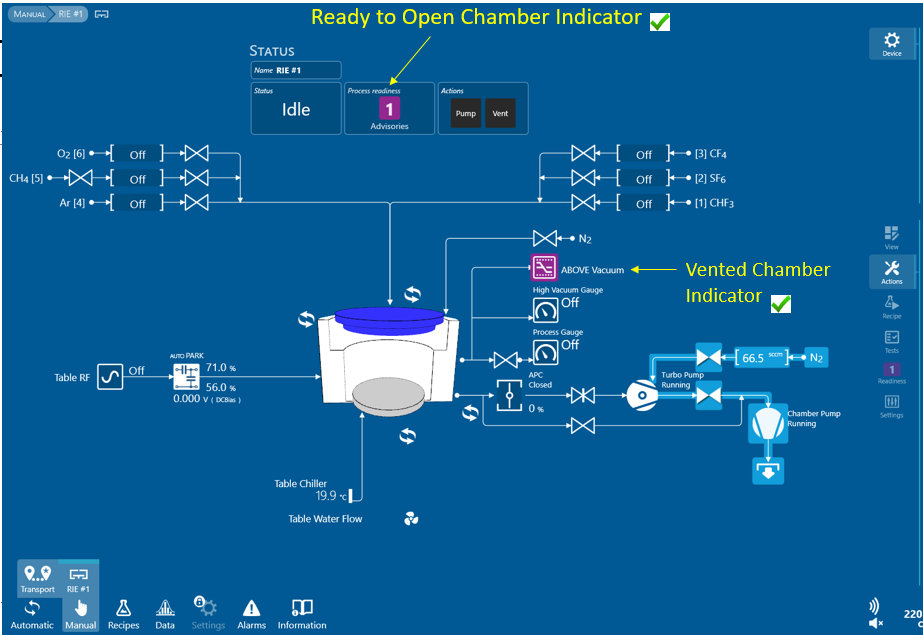
- Wait for the entire Vent process countdown to complete. When the countdown is complete, it will return to an “Idle” state and a purple “1” indicator will appear (See Photo). This typically takes about five minutes
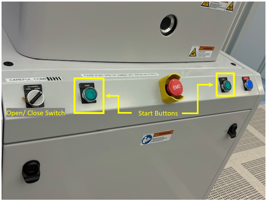
- Turn the Open/ Close knob on the tool to “Open” and hold down both green “Start” buttons simultaneously to open chamber. (See Photo)
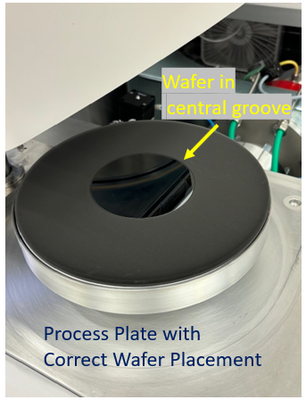
- Remove the white quartz cleaning plate, and insert the black graphite process plate. Be sure to align the screw in the surface of the tool chamber to the hole in the rear of the process plate. If you are using a carrier or conditioning wafer, place it in the groove at the center of the plate. The plasma will be strongest near the center of this circular groove.
- Turn the Open/Close knob on the tool to “Close” and hold down both green “Start” buttons simultaneously to close the chamber. The chamber is fully closed when it stops moving, and when the monitor displays an image of a closed chamber and only “1” purple indicator (not “2”).
- Click “Pump” in the Manual page to commence chamber pump down. This typically takes about 3-4 minutes.
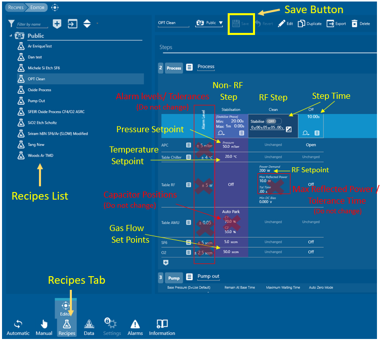
- Go to the “Recipes” tab in the lower menu to open the Recipe Editor page. Select your desired recipe from the recipe list on the left.
- Click on the “Step Time” number of the RF step, and it will change into a field that allows you to enter your desired conditioning/etch time. You must hit “Enter” to save the value and click outside the region to revert to the setpoint view. The “Stabilize” slider should always be “off” for this step.
- Click the “Save” Button Floppy Disk at the top of the screen. (If you do not save, your recipe changes will not register.)
Users should not create their own new recipes. Users should not change anything but the Step Time of the RF/ etching steps of a recipe unless explicitly permitted to do so. Under no circumstances should users change the gasses used, Alarm levels, Maximum Reflected Powers, Tolerance Times, or Capacitor Positions. If you need further recipe customization, please contact the tool manager.
Note- Any saved recipe changes will be permanent between sessions, so if you are allowed to change something beyond time please return it to the original setting when you are done
Note- The maximum reflected power is typically 5% of the forward power, not higher than 10% of the forward power, and not higher than 15W. Alarm level is typically \~5% of forward power and not higher than 5W. RF Power tolerance time is usually not higher than 10 seconds and should never be 0. If you observe an unusual value please contact tool manager.
Note- Processes in recipes are always sandwiched between “pump to base pressure” steps. The recipes must always end with APC open, RF off, gasses off, and temperature at 20C.
Note- Do not rely on a recipe to be identical to one you ran during another session just because the name is the same. Record all recipe setpoints when you run it and ensure they match desired values.
- Return to the “Manual” display.
- Ensure the pressure in the chamber has dropped to “Vacuum OK” status.
- Ensure that the chamber pressure has actually dropped to base pressure or lower (The base pressure for a process is 5x10⁻⁵ torr (0.05 mtorr).
- Click on the Upper-Right (not Lower Left!) “Recipes” Tab to open the “Process Recipe” Sidebar Menu.
- Select your saved recipe from the drop-down recipe menu and click “Start”
- Observe the process in the Manual Display. Ensure that actual process parameters match with setpoints, and that the “Reflected Power” value is always very low. You must stay in the cleanroom for the entire process. Stop the process and contact staff if you notice any unusual behavior.
- Accept Pop-up message in lower-right corner when process is finished.
If you need to prematurely stop a process step with hazardous gasses or materials, it is preferable to click “Skip Phase” rather than stop. This ensures any additional purge steps of the recipe are completed.
Note- The “Pause” button will stop RF power but will not stop the flow of process gasses
Note- Even after your plasma is off, you may still see small (\<1) or negative numbers in the forward or reflected power fields. This is normal and there is no active RF power/plasma present.
Note- Venting the chamber is the only time you should see any purple “Process readiness” alerts on the screen. If you see them at any other time (or anything else in the schematic that appears purple but usually isn’t) it usually indicates a tool issue. Contact staff if you observe this.
Ready To Open Main Chamber:
Tool Buttons for Opening/Closing Chamber:
Graphite Process Plate with Wafer:
Recipe Page:
Manual View During Process:
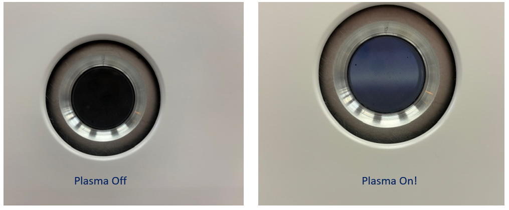
Note- Plasma glow will likely be visible from viewport when plasma is active:
- Etch Sample
Note - If attaching a chip to a carrier wafer, use only the smallest possible amount of Fomblin oil to adhere it to the center of the wafer and ensure even cooling. Apply evenly via the non-swab end of a swab so that the Fomblin oil is not visible after the chip is applied and ensure the chip doesn’t move when gently nudged by tweezers. (Chips poorly applied can be disturbed by the vacuum). Visible Fomblin oil may affect your process. Fomblin oil (or any liquid) should never drip to the underside of the carrier wafer. Running a first etch on a dummy chip may be beneficial.
- Once conditioning process is complete, follow the steps above for venting the chamber, inserting your sample, and running a recipe. Make sure any mandatory purges for hazardous gasses or toxic materials are performed before opening the chamber. Retain the black graphite process plate in the chamber, and change the RF step time to your desired etch time. The etch recipe will vary from your conditioning etch only by the time of the etch step.
- Remember to record your etch in the user log
Note- The double arrow  buttons may be used to change elements of the display. You can revert back to the original “hybrid” display via the “View” menu on the upper right hand corner. Some users may find the other, tabular display more convenient.
- Clean
(This cleans the instrument chamber, not anything else)
- Once your etch is complete, vent the chamber as described above. Make sure any mandatory purges for hazardous gasses or toxic materials are performed before opening the chamber.
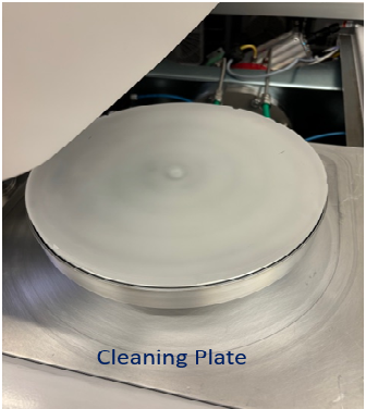
- Remove the graphite plate and insert the white quartz cleaning plate, (see photo) being certain to align the groove with the screw.
- “Load” the tool’s designated cleaning recipe and only change desired time. Clean for all active RF plasma time (conditioning + etching) plus 3 minutes. The Clean Recipe is “OPT Clean”. Make sure the table temperature is set to 20°C.
- Run process. Stay logged into Badger and in the cleanroom for the entire clean.
- Accept pop-up alert when finished.
- Ensure the tool is left under vacuum when done and Temperature is at 20C.
- Disable Badger
White Quartz Cleaning Plate:
Section 8: Emergency Stop
EMO Button
Only push this button if you feel you are in immediate physical danger- such as external arc flashing, sparks, or flames.
If you see arc flashing or sparks within the chamber through the viewport: First, stop the process in the software (“stop” button) or jump to the next non-plasma step (“Skip Phase” button) to quell the arcing. If this does not stop the arcing, this may warrant use of the EMO button.
A ticking noise during a plasma process accompanied by haywire RF numbers may also warrant use of the EMO button if attempting to stop it using the software doesn’t work first.
Section 9: What to Watch out for During Operation
Make sure desired gas flow and power values are consistently close to their setpoints, and that reflected power is always low.
When not in use, the table temperature should always be left at 20°C to avoid condensation build-up within the tool. Always make sure the Table temperature is at or approaching 20°C at the end of your session.
Section 10: Disallowed Activities
- This instrument incorporates hazards such as high-voltage electronics, radio-frequency radiation, UV- radiation, compressed gasses, heated parts, pinch- points, and vacuum chambers. Never attempt to tinker with the tool or software beyond what is explicitly described in this SOP.
- Oxidizing and flammable gasses should never mix. (eg- O2 and CH4 should never mix). If you ever observe it immediately stop the process and alert staff.
- The instrument should not be left at very low temperatures (0°C) for lengthy periods beyond what is needed for a process.
- Fomblin oil should never be heated above 250°C (may decompose to HF). This should not be a problem over the table temperatures we etch in (maximum 80°C), but keep this in mind for any post-process work.
- While you should keep an eye on your process periodically using the porthole, it's not advisable to stare deeply into it for lengthy periods with plasma running
When operating this tool, Users should never:
- Adjust Alarm levels, Maximum Reflected Powers, Tolerance Times, or Capacitor Positions
- Place an item that is not a wafer, chip, or slide in the open chamber! (Any other item requires special approval). Always make sure the chamber is clear of unusual objects or debris.
- Click “Continue” with a process that has alarmed
- Attempt to troubleshoot a problem themselves - photograph the alarm message or unusual behavior, contact staff, and await our instruction. If a process pauses due to an alarm and staff are not immediately available, be sure to “stop” the process.
- Place a new material in without gaining explicit approval from the etch tool manager via formstack. Anytime you want to change your process chemistry or put in a new material (regardless of whether or not it is etched), please submit a new form.
- Leave the tool vented or open when not in use
- Forget to run a clean at the end of the process.
- Leave the cleanroom while running a plasma process
- Operate in any mode other than Lab User
- Incorporate new gasses into a recipe that are not already utilized in that recipe or attempt to create a new recipe
- Run a clean on the graphite process wafer
Section 11: Revision History
Revision 2.0- New PTIQ Software, Formstack Process
Revision 3.0 – 5/29/25- Updated to meet lab-wide SOP standards and structure, other minor clarifications, gas clarification, correction on tolerance time. (Emma Anquillare)
Section 12: Signature Page
My signature below indicates that I have read this SOP and will abide by all rules and instructions.
| Name of Qualified User | Signature | Date |
|---|---|---|