Dektak Profilometer
Standard Operating Procedure: Stylus Profiler
Section 1 – Process or Experiment Description
This Standard Operating Procedure (SOP) outlines the proper use of the Bruker Detach -XT Stylus profiler. The Bruker Stylus Profiler is a semi-automated stylus profiler that can be used to measure step height with better than 5 Å repeatability, surface roughness, as well as 3D surface mapping.
All standard laboratory safety protocols must be followed throughout this procedure. While not all safety rules are explicitly stated within this SOP, they are covered in the required safety training sessions that must be completed prior to beginning any lab work. For instance, all personnel must wear appropriate lab attire, including an approved lab coat, safety goggles, closed-toe shoes, and clothing that covers all exposed skin, including the legs. A copy of the laboratory’s minimum safety requirements can be found in the SOP binder for reference.
Section 2 – Hazards General
| Hazard | Hazard Sign | Hazard Description |
|---|---|---|
| Mechanical Hazard Pinch Point |  |
The act of scanning your sample can cause the stage to move. Keep hands and fingers clear of sample stage while making measurements. |
Section 3 – Routes of Exposure
N/A
Section 4 – Process Steps
4.1. Working instructions
4.1.1 System Power Up
- Start the Vision64 software.
- Click OKAY when prompted to initialize the XY stage.
- Click Cancel when prompted to initialize the theta stage.
- The light over the sample stage should turn on once the stage is initialized and the software is open. Otherwise, restart the Vision64 software again.
4.1.2. Loading your sample and alignment
- Place sample in the center of the stage. Be careful not to touch the stylus tip whenever you load or unload a sample. Be sure the stylus is in its home position all the way up off the sample and stage.
- Note: You can position the stage for easier loading and unloading by clicking Unload Sample to move the stage out and clicking Load Sample to move the stage back in.
- Turn the vacuum on.
- Move the stylus down to the surface of the sample by clicking Tower Down. Be sure the stylus will touchdown on the sample. If it touches down off the sample, you risk crashing the tower into the sample, especially if the sample is thick. If the sample is going to touchdown off the sample, press Esc to stop its descent and reposition the sample before clicking Tower Down again.
- The stylus should move down to the surface until it touches, at which point it will lift back up and remain just above the sample surface. At this point, the sample surface should be visible and in focus on the display by means of the camera.
- Note: If you need to raise the stylus at all, you can move it up a few millimeters by clicking Tower Up, or you can move it all the way up by clicking Tower Home.
4.1.3 Collect Measurement Data
- In the XY and Theta control panels under Instrument Control, select the speeds at which you want to move and rotate the sample stage.
- Drag the red circle in XY control from the center of the cross-hair to move the stage to find the structure on your sample you intend to measure.
- Drag the red circle in the Theta control either clockwise or counterclockwise from the starting position to rotate the stage in order to orient your sample for measurement.
- Note: You can only measure in one direction, which is from bottom to top of the software display, so position your sample accordingly.
- In Measurement Options under Trace, select the Range and Profile best suited to what you are measuring.
- Determine the length of the measurement by either entering a value in micrometers into Length or click the Teach icon next to it. When prompted, move the sample to the position from which you want the measurement to start and then click Next, then move the sample to the position where you want the measurement to end and then click Done.
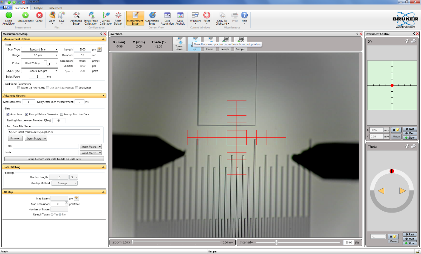
- Determine the Resolution of your measurement by entering a value in seconds into Duration. Longer scans will resolve smaller structures and thus have better resolution.
- Note: If you wish to perform a sequence of measurements, perform data stitching, or create a 3D map, those options are also available under Measurement Setup, but they are not necessary for a typical measurement.
- Once your measurement parameters are entered, click Single Acquisition to make the measurement. Do not touch or bump the table holding the Dektak-XT while it is measuring, as any wobbling could ruin the measurement.
4.1.4. Data Analysis
- After the system has made a measurement, the software will switch to the Data Analysis window.
- Level the data if necessary, by selecting Terms Removal (F-Operator) in Data Analyzer, then move the R and M cursors to two points you expect should be level and then right-click the data and select Two-Point Leveling.
- Note: There are many options for filtering and analyzing data available in Data Analyzer. For information on the different options, consult a Bruker manual.
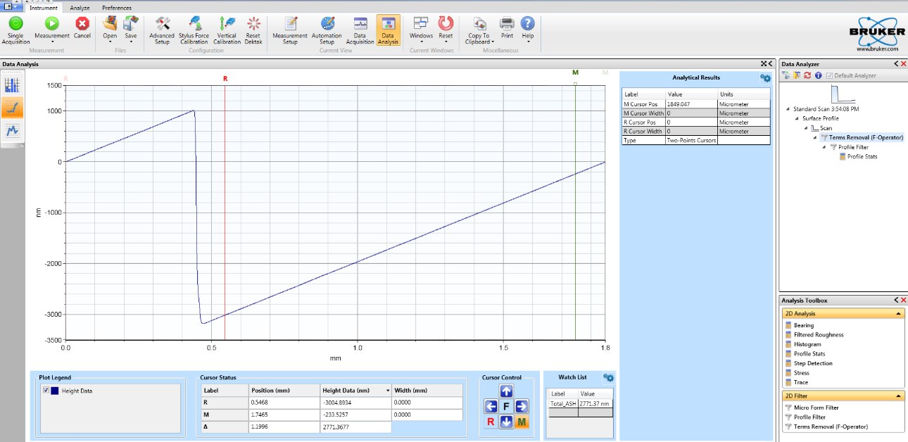
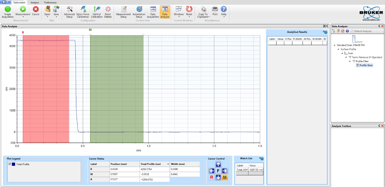
- Make measurements by moving the R and M cursors to positions you wish to compare and then expand them in order to average over certain portions of the measurement.
- A value for Total_ASH (average step height) determined from the difference between the average heights of R and m will be displayed in Watch List.
- Note: Watch List can be configured to display other data that you may wish to measure.
4.1.5. Save data
Save the data set using the file operation functions. Save → Dataset. You should save your data to your own folder in the NanoFab01 network drive either in the XML or Bit map format.
4.1.6.Unloading sample and Shutdown Tool
- Navigate to the Measurement Setup window.
- Click Tower Home to raise the stylus back to its home position.
- Turn the vacuum off.
- Unload your sample.
- Close the Vision64 software. The light over the sample stage should turn off once the software closes.
- Clean up the work area.
Section 5- Allowed Activities
Users should only attempt to make measurements with the tool configured as it is. Anything that requires a different configuration should not be attempted without first consulting cleanroom staff.
Emergency stops should not be necessary for this tool, but if circumstances ever arise where it is necessary to perform an emergency stop, do so by pressing the red EMO button on the tool’s controller.
Section 6-Disallowed Activities
Do not disconnect any cables when the system is powered on.
Never try to change the stylus tip. The stylus tip will break if handled improperly.
Users should not attempt to calibrate the tool. If they do not believe the tool is properly calibrated they should inform the cleanroom staff.
Section 7- What to watch out for during operation
Avoid any vibration and shock during measurement.
Always keep the environmental enclosure door closed when the system is in use and idle
Be mindful of the limits your sample might impose on measurements. The stylus may not be able to properly measure some features that are too deep and too narrow. Issues may arise where the stage may get stuck in a position and the software will stop responding. Attempt to close and restart the software, reinitializing all of the stages in the process. Notify staff if this occurs.
Section 8 - Common Troubleshooting Tips
If something is not responding, attempt to close and restart the software, reinitializing all of the stages in the process. Notify staff if this occurs.
Section 9- When to call staff?
If the stage is not working. Or if the stylus is broken.
Section 10- Badger Criteria
Report Problem:Shutdown:
If the Stylus is broken or the stage is not working. Report this in Badger and send a message to staff.